Dipole trap construction
Table of Contents
I construct loading coils by winding RF David Flexweave insulated antenna wire around PVC couplers. Magnet wire may be cheaper and can be wound into tight coils for higher inductance, but flex weave requires far less strength, and the result is a neater coil (easier to reproduce). I generally wind the coils with 14awg.
Speaker wire is a cheaper option for winding coils and should be about as easy to work with as flex weave.
First see my post on [designing a trapped dipole][designing-trapped-dipole] for context.
Materials required
- PVC Couplers
- Insulated wire
- High voltage capacitors
- Ring terminals + crimp tool
- Mechanical copper lugs
- Nano VNA
- Screws and nuts
- I used 12AWG ring terminals, 14AWG lugs and M8 screws.
How I build traps
I’ll demonstrate my process for constructing parallel LC circuits, to be used as dipole traps.
Calculate initial coil dimensions
66pacific.com has a nice online tool which performs this calculation. Unless I’m lucky, this will only give me a starting point for your coil. Since I use fixed-value capacitors, I’ll need to compensate by adjusting the inductance higher or lower in order to make our trap resonant on the higher frequency band.
Build air-coil with pvc coupler
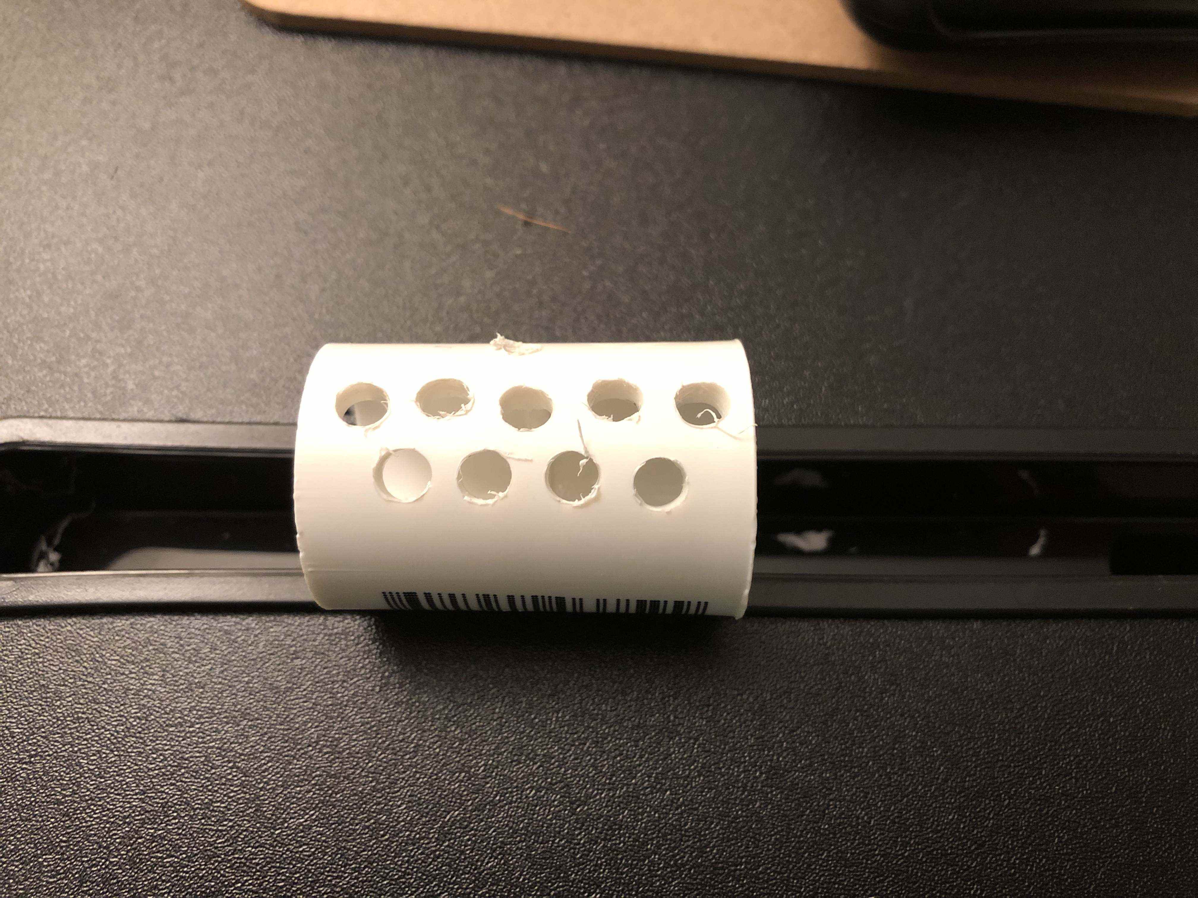
First, I drill a series of holes in the PVC coupler, which allows for easy adjustment of inductance.
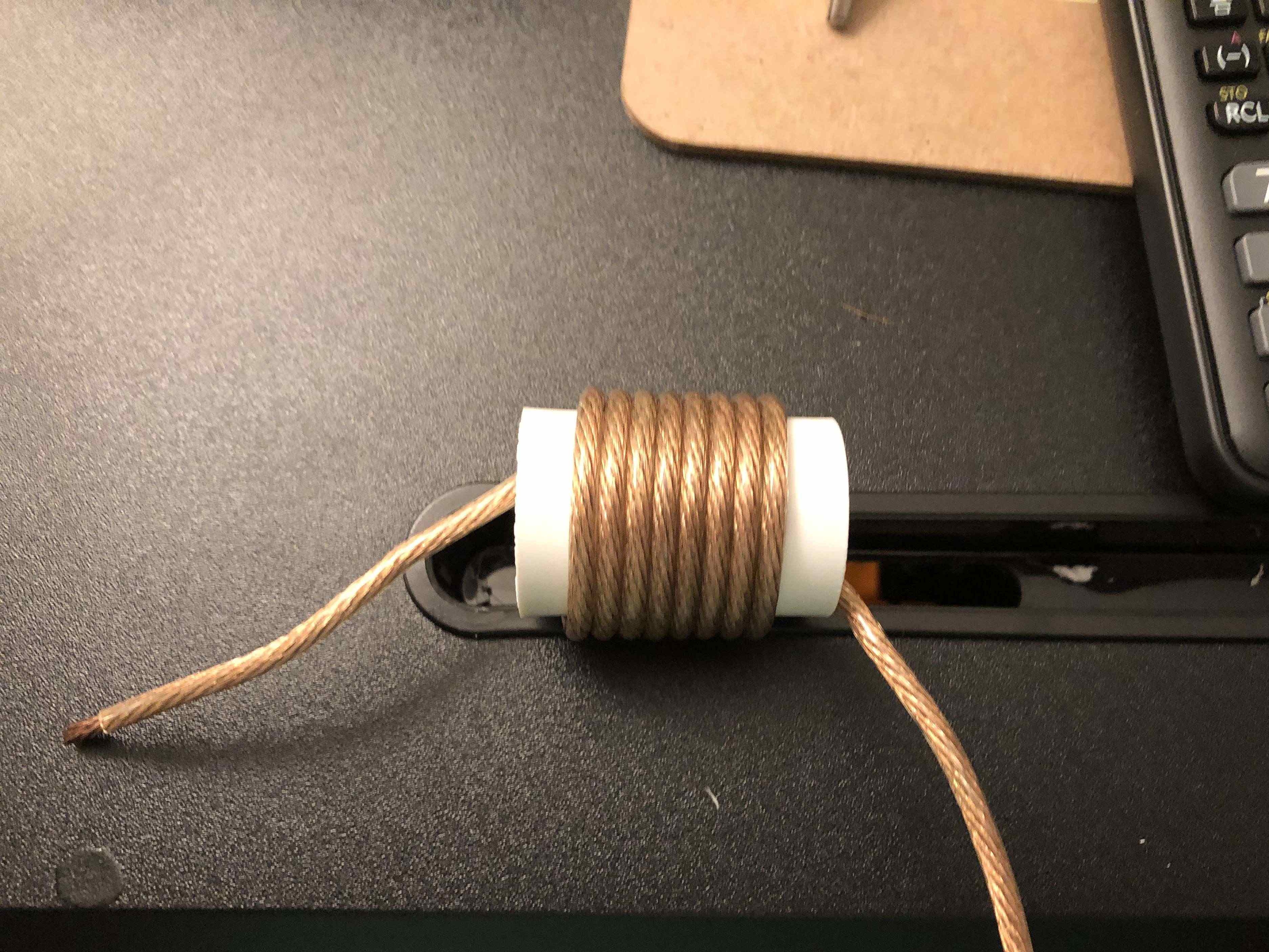
Then, I wind the inductor and add 2-3 more turns of wire than I’ve estimated. Later I must “tune” the inductor and it is easier to remove wire than to add it.
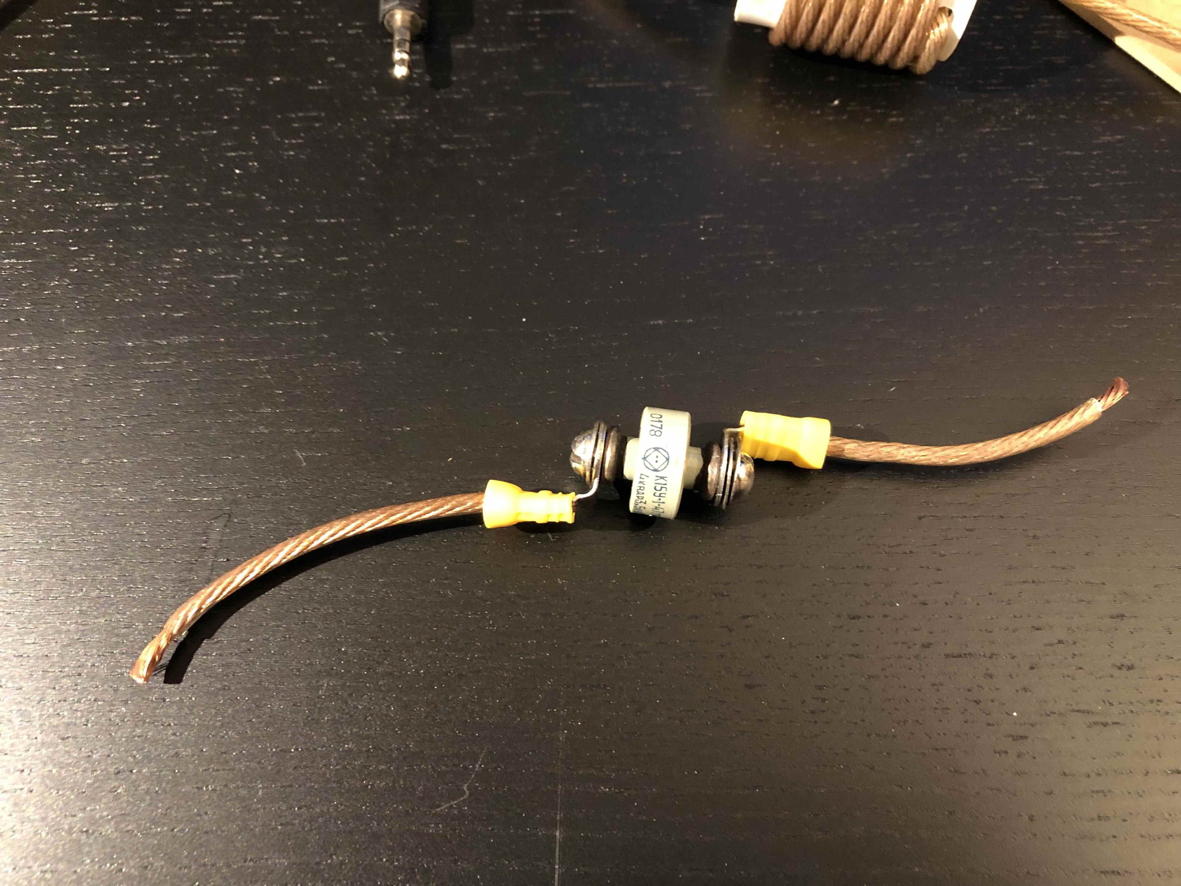
Next, I attach lead wires to the capacitor, using ring terminals.
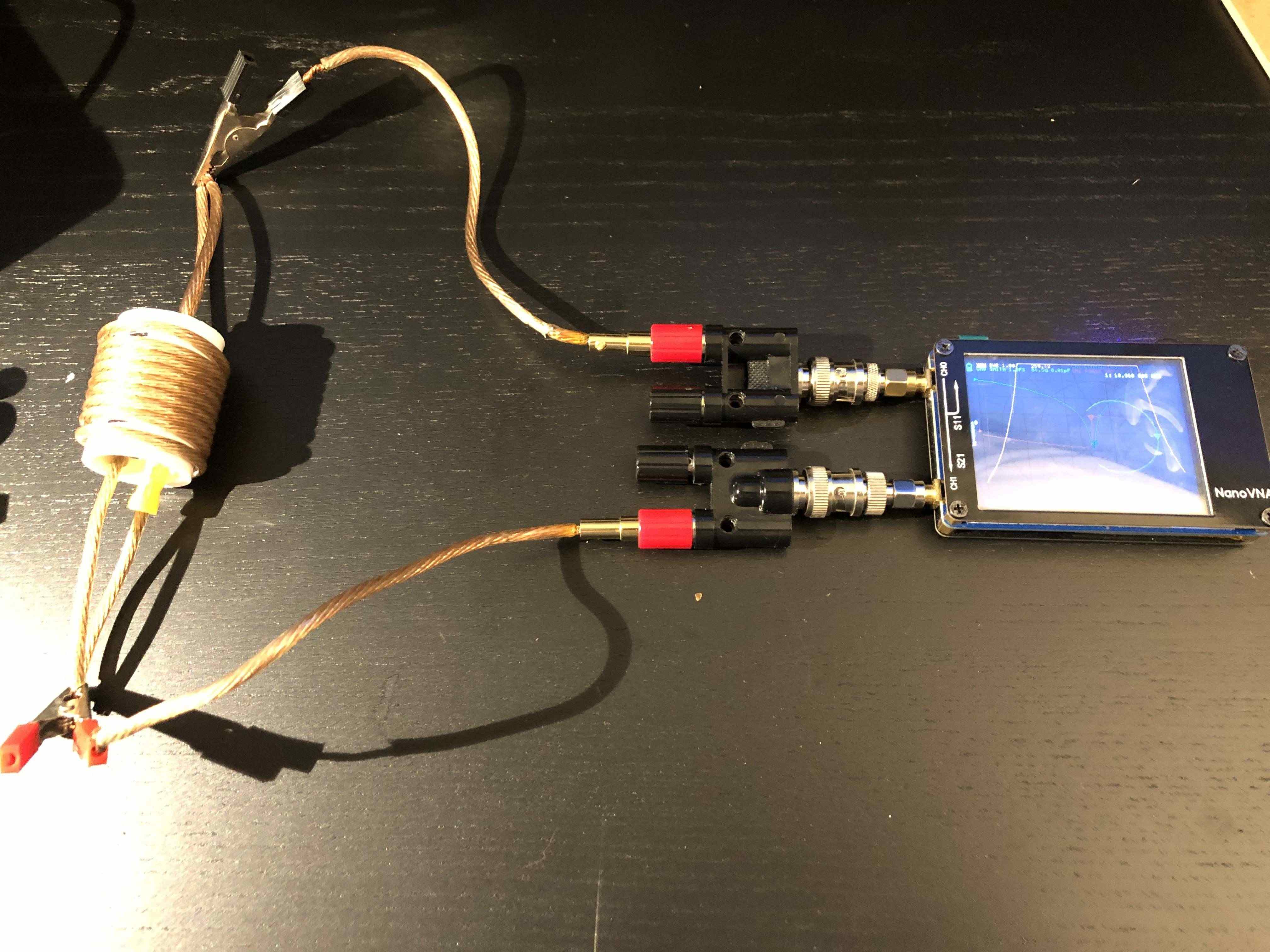
I then clip the leads of the inductor and capacitor in parallel and connect to the Nano VNA and observe trap resonance (see notes below on measuring trap resonance with a Nano VNA).
Now, I “tune” the inductor for trap resonance. The relationship between resonant frequency and inductance is inverse:
\[f_{resonance} = \frac 1 {2π\sqrt {LC}}\]So if resonance is low, inductance is too high and our coil must be shortened and if resonance is too high, inductance is too low and our wire must be lengthend.
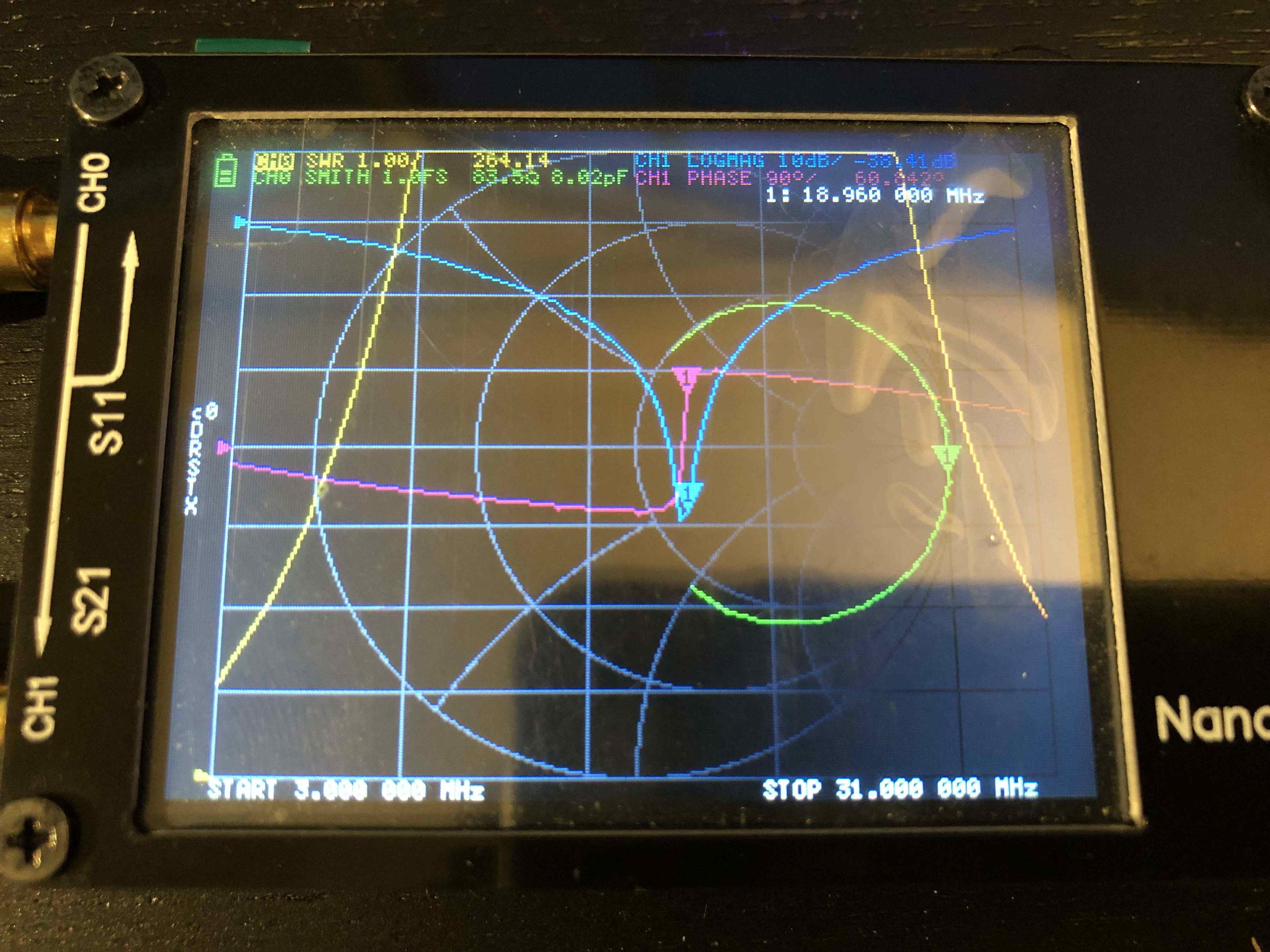
For this trap, I want resonance close to 18.118MHz. 18.960MHz might be a bit too high (see notes from W8IJ below). Since I didn’t actually start with extra turns, I must now cut a new, longer piece of wire and start over.
Instead, I’ll cheat. By pressing the windings closer together, I can literally squeeze a bit more inductance out of this coil :)
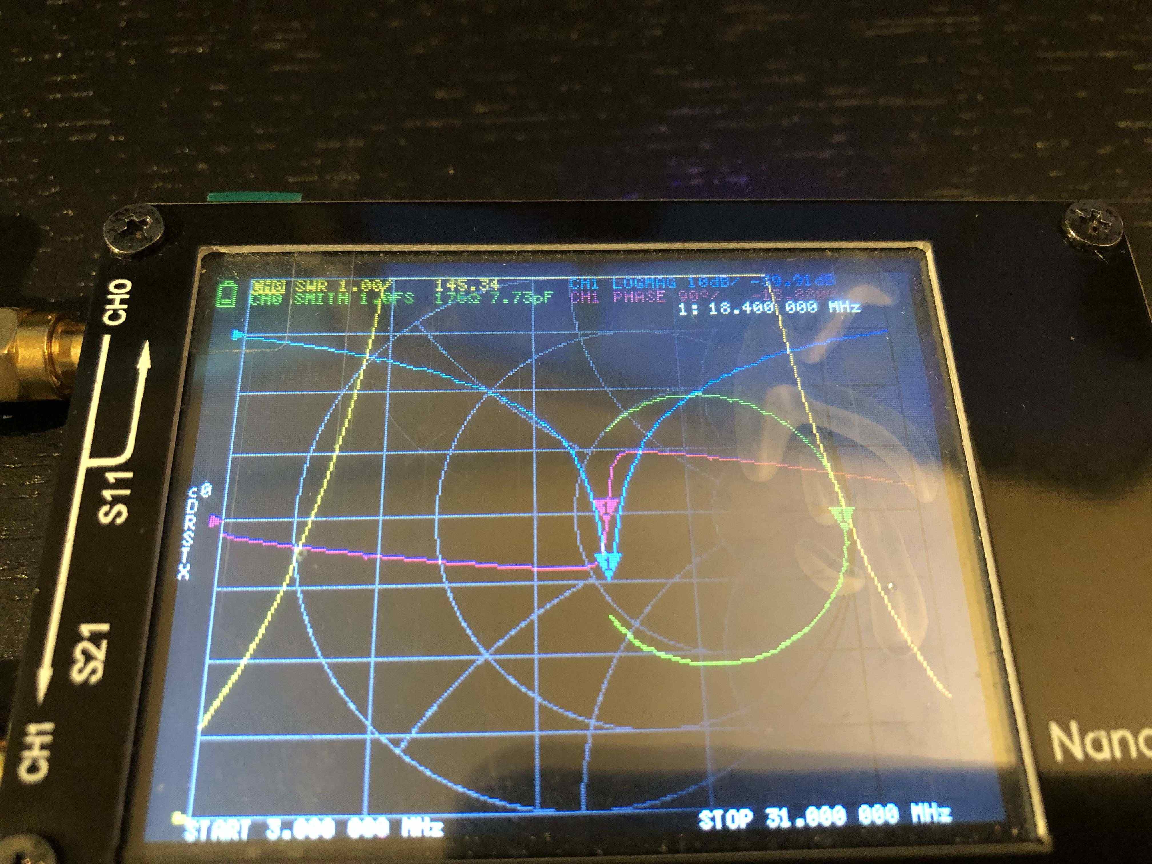
18.400MHz might not seem close enough, but according to W8IJ, dipole traps do not need perfectly resonant. In fact, it’s preferable that their resonance be a bit off, since losses are higher with traps that are perfectly resonant. In fact, it’s possible that resonance at 18.960MHz will work just as well.
This is good news for me, since perfectly resonant traps would require perfectly wound coils. Tuning for resonance within 500KHz is hard enough.
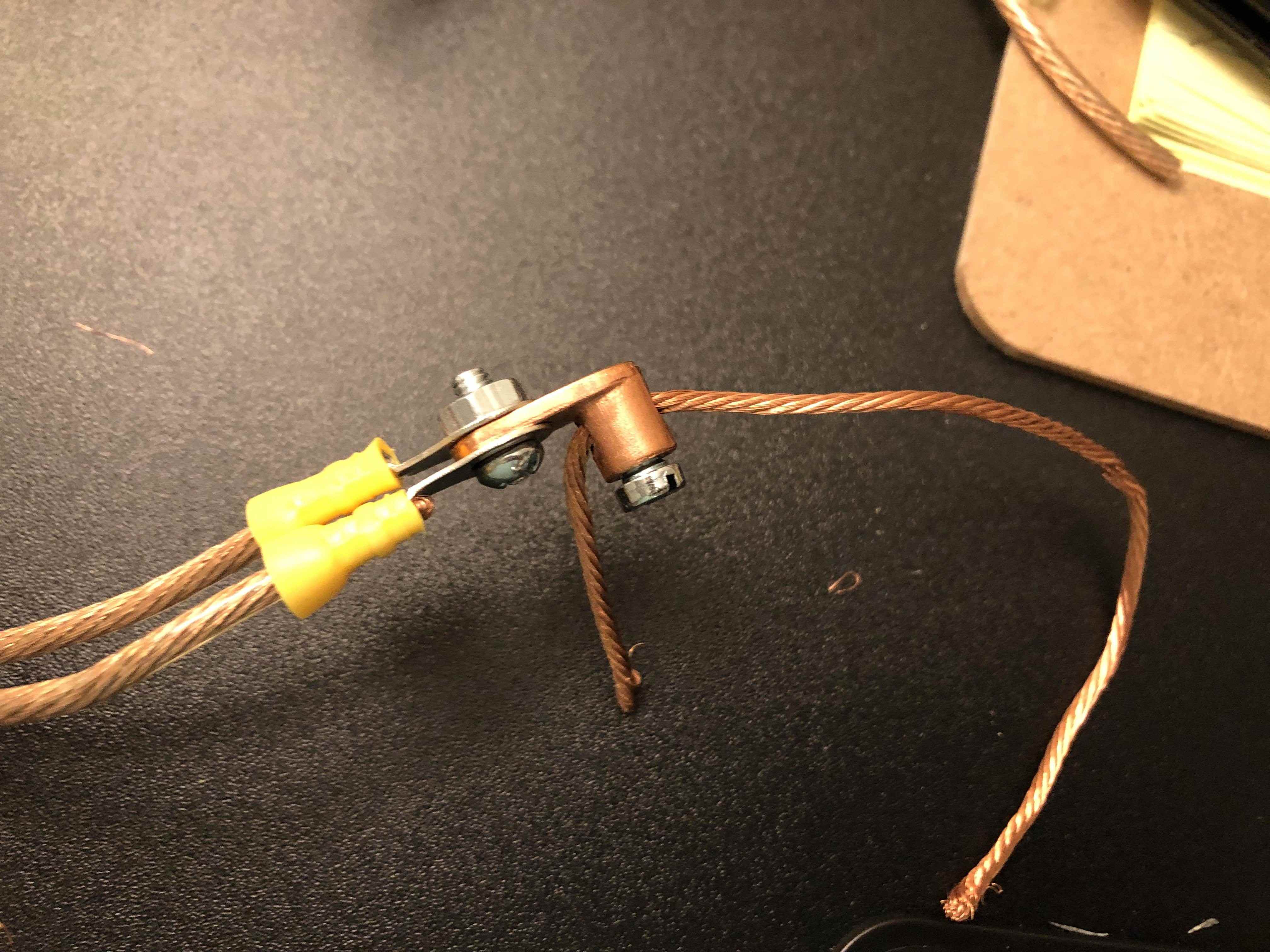
Finally crimp leads onto the inductor and capacitor leads and screw them together with the copper lugs. By keeping the inductor leads shorter, tension will be applied to the PVC (instead of the capacitor).
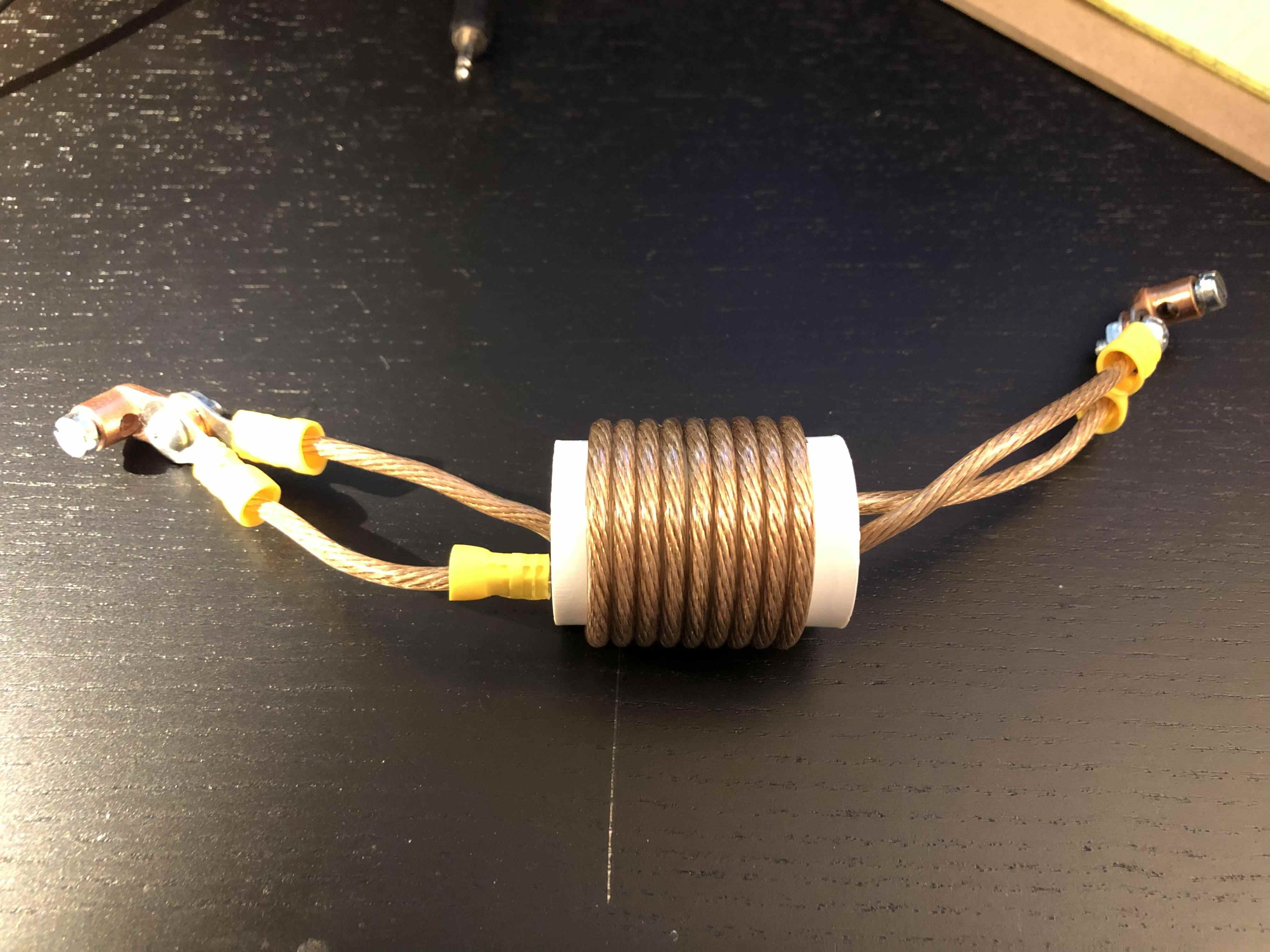
With these copper lugs, I will have a much easier time assembling and tuning the antenna later.
It can take some time to get the turns right and to “tune” your trap to resonance. Fortunately, it’s very easy to build the second trap by copying the first. Remember, I do not need perfectly resonant traps.
However, you might not have an easy time reproducing the same resonance if you wind your traps with magnet wire and get this:
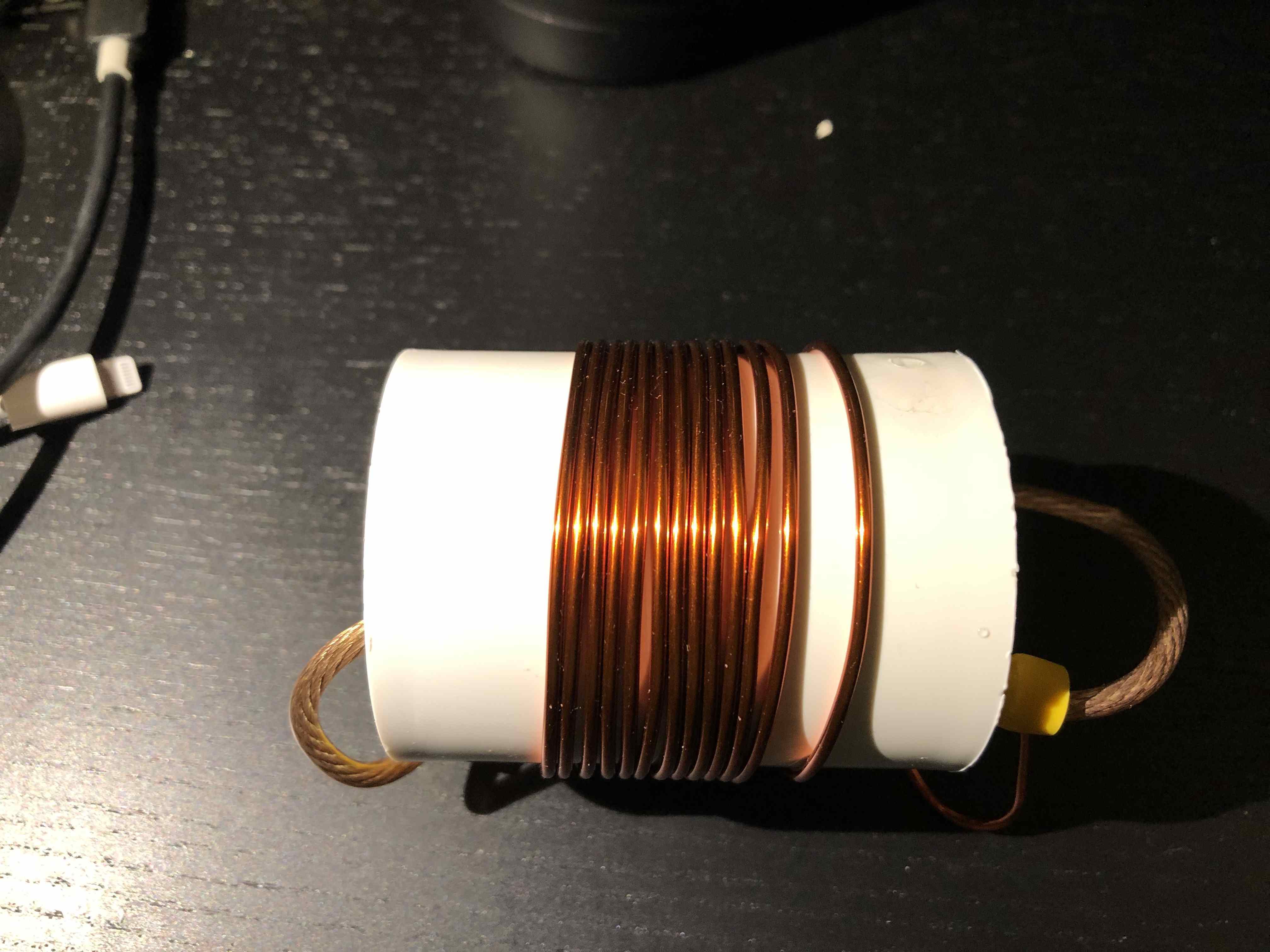
Spaces between windings (hard to avoid with magnet wire) will lower inductance in a way that is hard to reproduce. It’s true that winding spacing increases Q and lowers loss, but it’s much easier to produce coils with consistent inductance with tighter windings.
If I want to go cheaper next time, I’ll try speaker wire.
Resonance measurements
I know of two methods, using a Nano VNA, to measure trap resonance.
Channel 1 signal loss
Shown above, I connect the trap to the center-pins of Channel 0 and
Channel 1 on my Nano VNA. I’m interested in the CH1 LOGMAG graph.
Since traps inhibit RF at frequency resonance, I am looking for a sharp
drop in signal strength. That’s exactly what I find: -39dB of signal
strength loss at 18.400MHz.

This method requires a two port VNA.
VNA as a “grid-dip” meter
With a single port analyzer, I can run a loop from the center pin
conductor to ground, without making any other electrical connections,
and observe CH0 SWR.
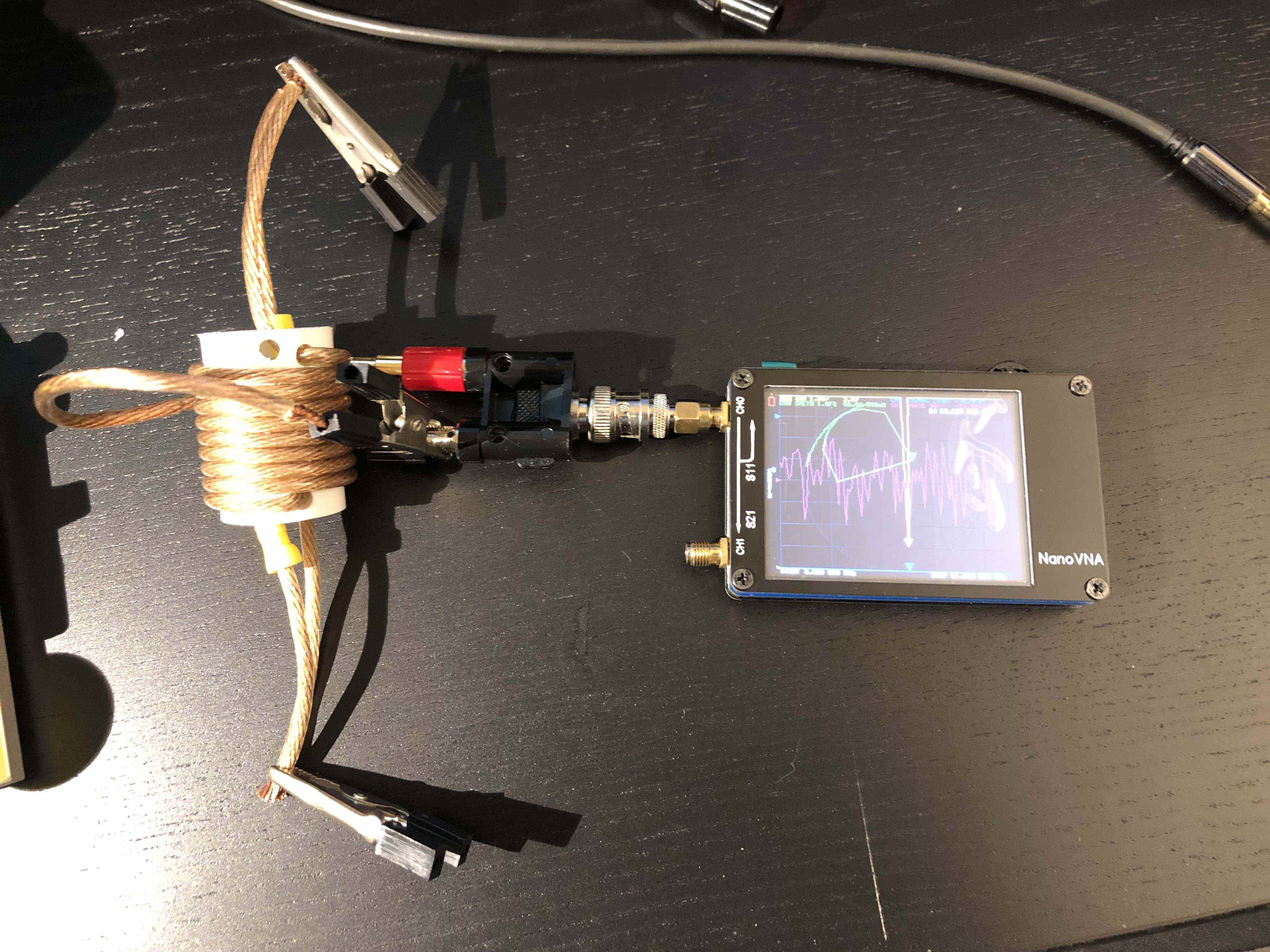
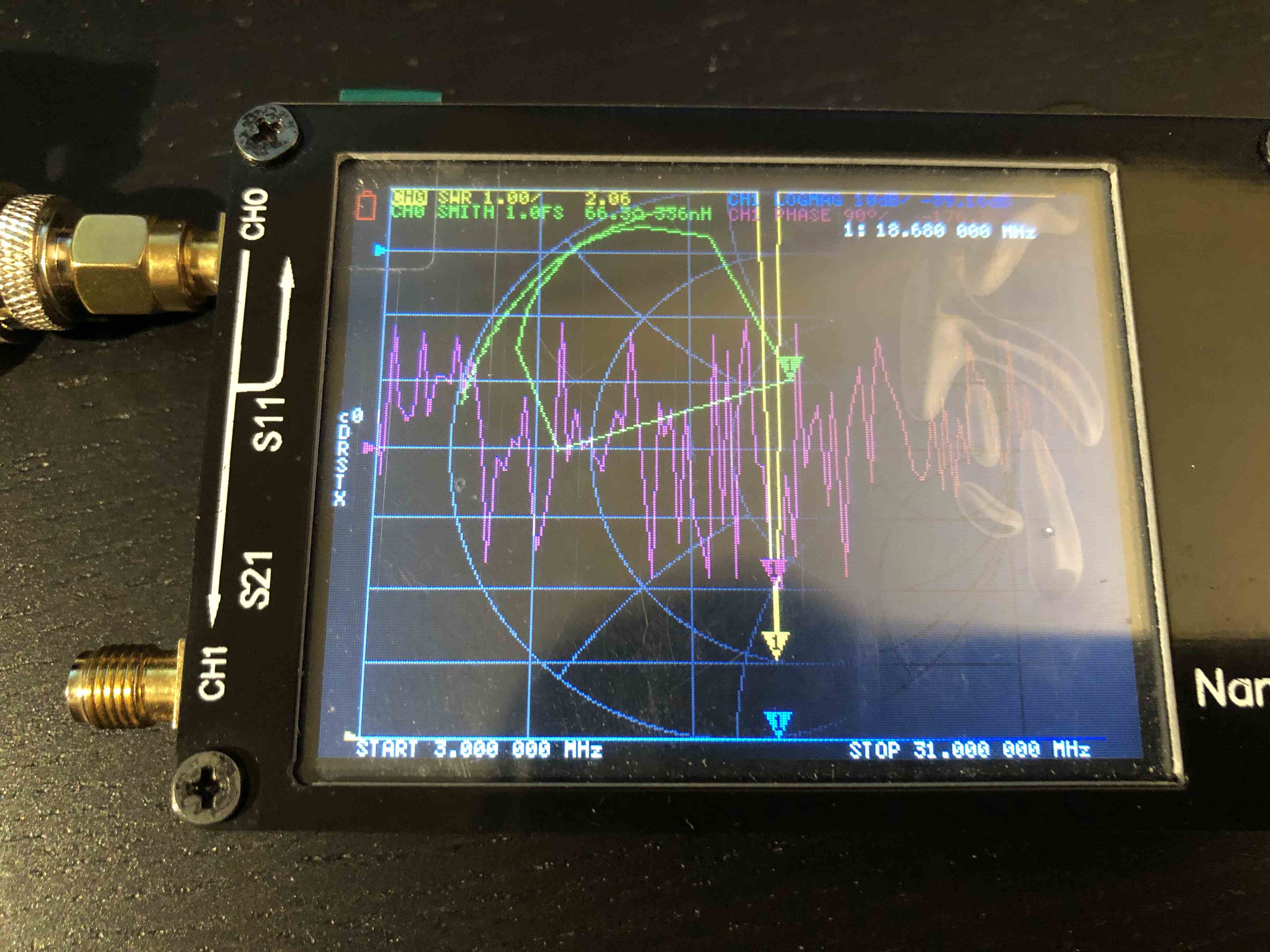
Example from a separate trap.
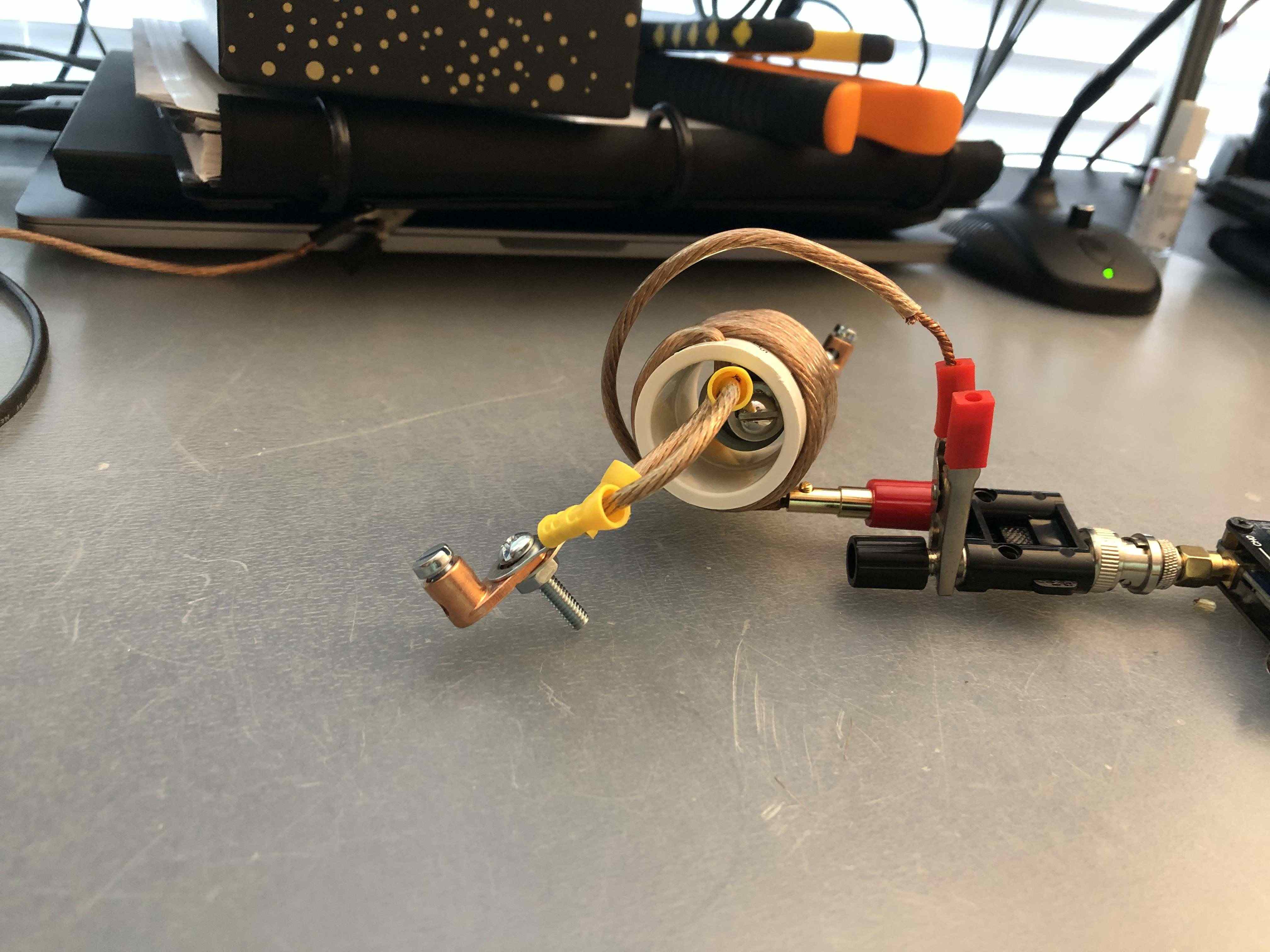
I can’t explain why this works, but I can validate that the SWR dips at trap resonance. You might have to wiggle the loop to see the SWR dip, but it’ll work.